A unit that reaches its temperature setpoint can still be underheating the process, consuming excessive power, or operating close to a damaging pressure or temperature limit. By recording the right measurements before resetting the machine and following a fixed sequence from water flow to controls and refrigerant circuits, you can separate a load problem from a heat-pump fault.
Key takeaways
- Calculate temperature lift from leaving-source and leaving-sink temperatures.
- Check flow, fouling, trapped air, and water instability before replacing components.
- Separate electrical, control, and refrigerant faults using measured readings.
- Compare measured heat duty and COP before repairing, staging, or replacing equipment.
Start with temperature lift, heat duty, and the pre-reset record
Measure temperature lift before changing a setpoint: subtract the leaving-source temperature from the leaving-sink temperature, using kelvin for the difference. Compare the result with the design lift, because the ideal COP is T_sink divided by T_sink minus T_source; compressor, motor, heat-exchanger, and control losses make the actual COP lower.
A high leaving-water temperature does not prove adequate capacity if process flow is below design.
Before resetting, preserve the operating evidence:
- Entering and leaving temperatures on the source and sink circuits
- Measured flow rate and calculated heat duty
- Suction and discharge pressures
- Compressor discharge temperature and current
- Ambient temperature, operating setpoint, and alarm code
- Defrost status, cycle duration, and time since the previous trip
Calculate liquid-water duty as mass flow multiplied by specific heat capacity and temperature rise. Compare that duty with the required process load, not only with the outlet-temperature setpoint.
| Finding | Evidence | Likely conclusion |
|---|---|---|
| Inadequate capacity | Normal lift, but measured duty remains below process demand | Load exceeds available compressor or heat-exchanger capacity |
| Excessive lift | Large source-to-sink temperature difference, rising discharge temperature, falling COP | Improve source temperature, reduce sink temperature, clean exchangers, or stage the load |
| Genuine equipment fault | Duty, flow, and lift were previously normal, then a sensor, pressure, current, or temperature value departs sharply | Continue industrial heat pumps troubleshooting with electrical, hydraulic, controls, and refrigerant tests; do not keep resetting the unit |
Trace low flow, fouling, air, and unstable water circuits
Industrial heat pumps troubleshooting starts by proving the water-side numbers, not by resetting the alarm. Calculate heat duty from measured flow and temperature change: Q̇ ≈ ṁ × cp × ΔT for water. A high leaving-water temperature proves only that the setpoint was reached; below-design flow can produce little total heat.
Record entering and leaving temperatures, flow rate, pump differential pressure, suction and discharge pressures, discharge temperature, compressor current, and alarm state at steady operation. Compare the readings with the design flow and the manufacturer’s operating envelope.
- Reduce demand or adjust the control valve while watching flow and leaving-water temperature. If low flow causes the leaving temperature to rise, duty to fall, or high-pressure trips to recur, the hydraulic circuit is implicated.
- Check the strainer, filter, isolation valves, check valve, control valve position, and pump speed. A rising pressure drop across a strainer identifies blockage; a falling pump differential with unstable flow points to cavitation, air ingress, or pump control.
- Compare the heat-exchanger approach temperatures. A growing approach with normal refrigerant pressure indicates fouling or scale, which increases lift and power consumption.
- Vent trapped air at high points and inspect the expansion tank, automatic air separator, and pump suction. Bubbles, fluctuating flow, and swinging temperatures prove an unstable water circuit.
- For air-source industrial heating equipment, inspect coil frost, airflow, drain paths, and defrost timing. Frost raises air-side resistance and can cause icing, low suction pressure, and repeated trips.
Separate electrical, controls, and refrigerant faults safely
Lock out power before opening panels or refrigerant circuits. Confirm phase-to-phase voltage, phase sequence, and compressor-current balance; a missing phase or large current imbalance points to supply, contactor, or motor wiring trouble, not refrigerant. Compare every temperature sensor with a calibrated probe and its resistance or voltage chart.
An open, shorted, or implausible reading identifies the sensor circuit.
Use the controller’s commanded expansion-valve position alongside actual superheat and pressure response. A valve that hunts, remains fixed, or fails to change superheat directs you toward the valve, driver, wiring, or sensor. Do not force the valve open while liquid return could damage the compressor.
- Record suction and discharge pressure, suction and discharge temperature, superheat, subcooling, current, and ambient temperature before adjustment.
- Check for a temperature drop across the filter-drier, solenoid, or liquid line; a sharp drop with low suction pressure indicates restriction.
- Confirm charge against the manufacturer’s weighed charge and leak history, then verify superheat and subcooling. Do not add refrigerant as a guess.
| Fault | Distinguishing test | Likely finding |
|---|---|---|
| Undercharge | Low suction, high superheat, low subcooling | Insufficient liquid feed |
| Overcharge | High head pressure, high subcooling, receiver backup | Excess liquid inventory |
| Restriction | Temperature drop across restriction, high superheat | Blocked drier, valve, or line |
| Non-condensables | High head and discharge temperature with excessive subcooling; recover, evacuate, and weigh charge | Air or other trapped gas |
| EVI fault | Check intermediate pressure, injection-valve feedback, subcooling, and injection heat-exchanger temperatures | Control, piping, or valve problem |
Repeated high-discharge trips demand this sequence, not a higher trip setpoint. This measured approach is central to industrial heat pumps troubleshooting.
Diagnose EVI faults, frost, short cycling, and extreme lift
An EVI heat pump problem is not confirmed by low suction pressure alone. Compare the controller’s injection command with actual injection pressure and line temperature, then inspect the electronic expansion valve, solenoid, strainer, sensor wiring, and flash-tank conditions. A failed valve or sensor can remove injection while the main circuit still appears to run.
Use these checks when the fault appears only under difficult conditions:
- For frost, record ambient temperature, humidity, airflow, coil temperature, fan operation, drain clearance, and defrost start and termination. Ice returning after defrost points to inadequate airflow, a blocked drain, poor defrost control, or low refrigerant—not automatically to a dirty coil.
- For short cycling, log compressor run time, off time, entering-water temperature, demand changes, deadband, flow, and active capacity steps. Intermittent process demand combined with low water volume causes rapid starts; increasing deadband, adding correctly sized buffer storage, staging compressors, or applying variable-speed control addresses the cause.
- For extreme lift, calculate actual source and sink temperatures in kelvin and include both heat-exchanger approach temperatures. Fouling can increase lift while pressures look normal, so rising power and falling heat output matter.
- If one circuit must span a very large lift, compare it with cascade or staged operation. Splitting the lift can improve compressor conditions, but adds heat exchangers, controls, failure points, and commissioning work.
Do not cure short cycling by oversizing the unit; excess capacity worsens cycling and part-load losses. Industrial heat pumps need a measured operating sequence, not repeated resets.
Use measured performance to choose repair, staging, or replacement
Approve a repair only when a controlled test shows that the unit now delivers its specified heat duty at the measured source and sink conditions. Record flow, entering and leaving temperatures, suction and discharge pressures, discharge temperature, compressor current, total electrical input, ambient temperature, defrost status, and alarm history.
Calculate liquid duty as mass flow × specific heat × temperature rise, then state whether COP includes pumps, fans, controls, heaters, and defrost.
| Decision | Measured evidence | Action |
|---|---|---|
| Repair | Duty, temperatures, pressures, current, and stable operation return to the recorded design or commissioning values | Release the unit after a loaded endurance test |
| Buffer storage | Demand repeatedly falls below minimum capacity, with frequent starts and stops and little water volume | Add correctly sized buffer storage and retune deadband |
| Staged circuits | Load changes in steps, while one compressor cannot follow efficiently across the operating range | Use staged compressors or separate circuits with sequenced controls |
| Supplementary heat | Source heat is unavailable during peak demand or the required lift makes duty and COP unacceptable | Add backup heat for defined peaks, defrost, or recovery periods |
| Different configuration | Required duty is absent despite correct flow and sound components, or source and sink loads are not simultaneous | Reconfigure industrial heating equipment, storage, or heat recovery |
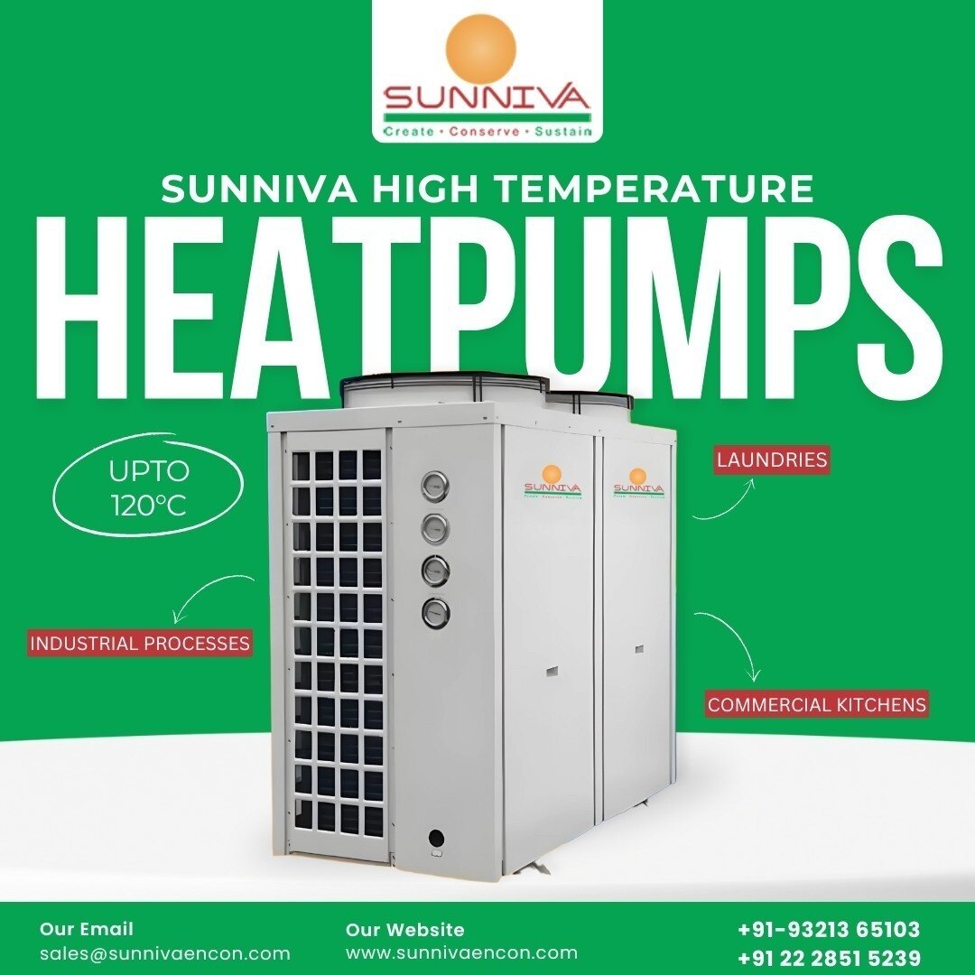
Do not judge success from outlet temperature alone: low flow can reach setpoint while transferring too little heat. For industrial heat pumps, test at minimum, normal, and peak loads. SUNNIVA HEAT PUMPS is one supplier to ask for the declared COP boundary and measured commissioning data before comparing equipment.
Frequently asked questions
How do you calculate temperature lift in an industrial heat pump?
Subtract the leaving-source temperature from the leaving-sink temperature and express the difference in kelvin. Compare it with the design lift.
What causes low flow in industrial heat pumps?
Inspect strainers, pumps, valves, blocked heat exchangers, trapped air, and unstable water circuits before investigating refrigerant faults.
How can you separate electrical, controls, and refrigerant faults?
Review alarms and sensor readings, verify supply voltage and control signals, then use qualified service procedures for pressure and refrigerant checks.
What are common EVI heat pump problems?
Check the electronic expansion valve, injection temperature and pressure sensors, injection piping, frost buildup, and compressor operating limits.
When should you repair, stage, or replace industrial heating equipment?
Use measured heat duty, temperature lift, power input, COP, fault frequency, and operating limits to compare each option.